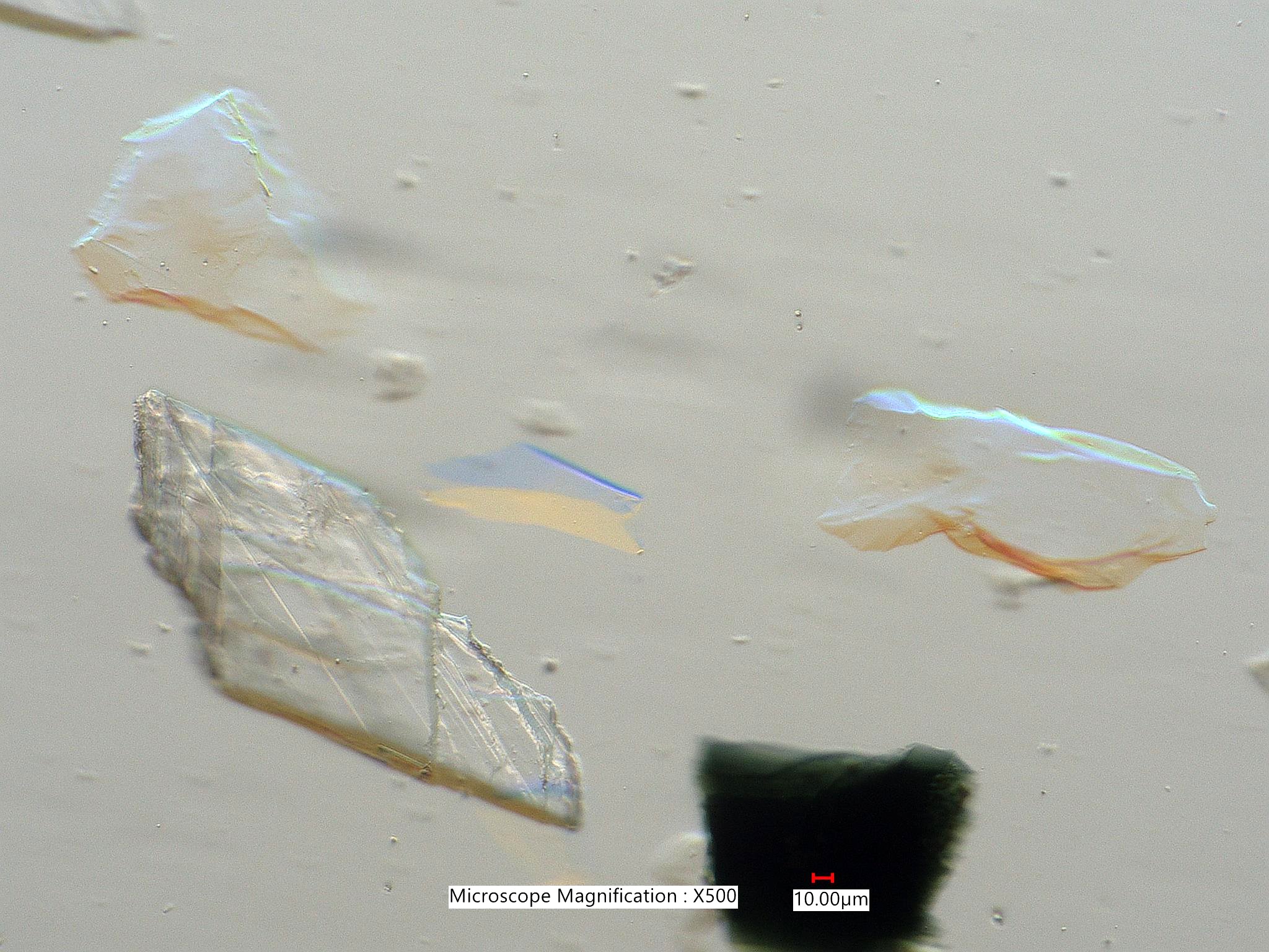
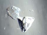
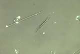
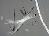
Interface PropertiesFeatures evident at the interface between the particle and the adjacent medium.  Relative Refractive IndexThe relative refractive index referes to the difference in the real part of the refractive index, "n" of the particle minus "n" of the medium (npart - nmedium). The greater the difference, either positive or negative, the darker the bondary of the particle. This is presented in more detail under "Relief". Relative AbsorptionRelative Absorption (kpart - kmedium): The refractive index is a complex number having both a real and an imaginary parts. The imaginary part is the absorption coefficient and is designated as "k". The higher the imaginary part of the refractive index the darker the particle. ReliefRelief, simply speaking, is the contrast at the edge of a particle as a result of differences in the refractive index between the particle and the mounting medium. John Delly provides a more detailed definition in his book, ESSENTIALS OF POLARIZED LIGHT MICROSCOPY AND ANCILLARY TECHNIQUES. His definition is "Contrast between a specimen and its surroundings (typically mounting media) due to the difference between their refractive indices. The greater the numerical difference in refractive indices, the stronger the relief. Expressed as positive or negative; high, medium, or low." . . . Glass Fiber and Silica Phytoliths in 1.485 refractive index mounting mediumThe first image shows a glass fiber from an office ceiling acoustic tile. The refractive index of the glass fiber is about 1.520. The relief is moderate. The sign cannot be determined, positive or negative, from this image. If it were negative, refractive index lower than the mounting medium, then the fiber would become dark when the stage is lowered (bright Becke line out). If it were positive, refractive index higher than the mounting medium, then the fiber would become bright when the stage is lowered (bright Becke line in). 
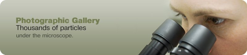
This image shows a glass fiber (lower left) and a silica phytolith (upper right) with oblique illumination. The light is coming in from the right. The silica phytolith has a lower refractive index, relief is negative, and so is bright on the right. The glass fiber has a higher refractive index, relief is positive, and is dark on the right side. With oblique illumination the relative refractive index can be determined without having to defocus the particle. 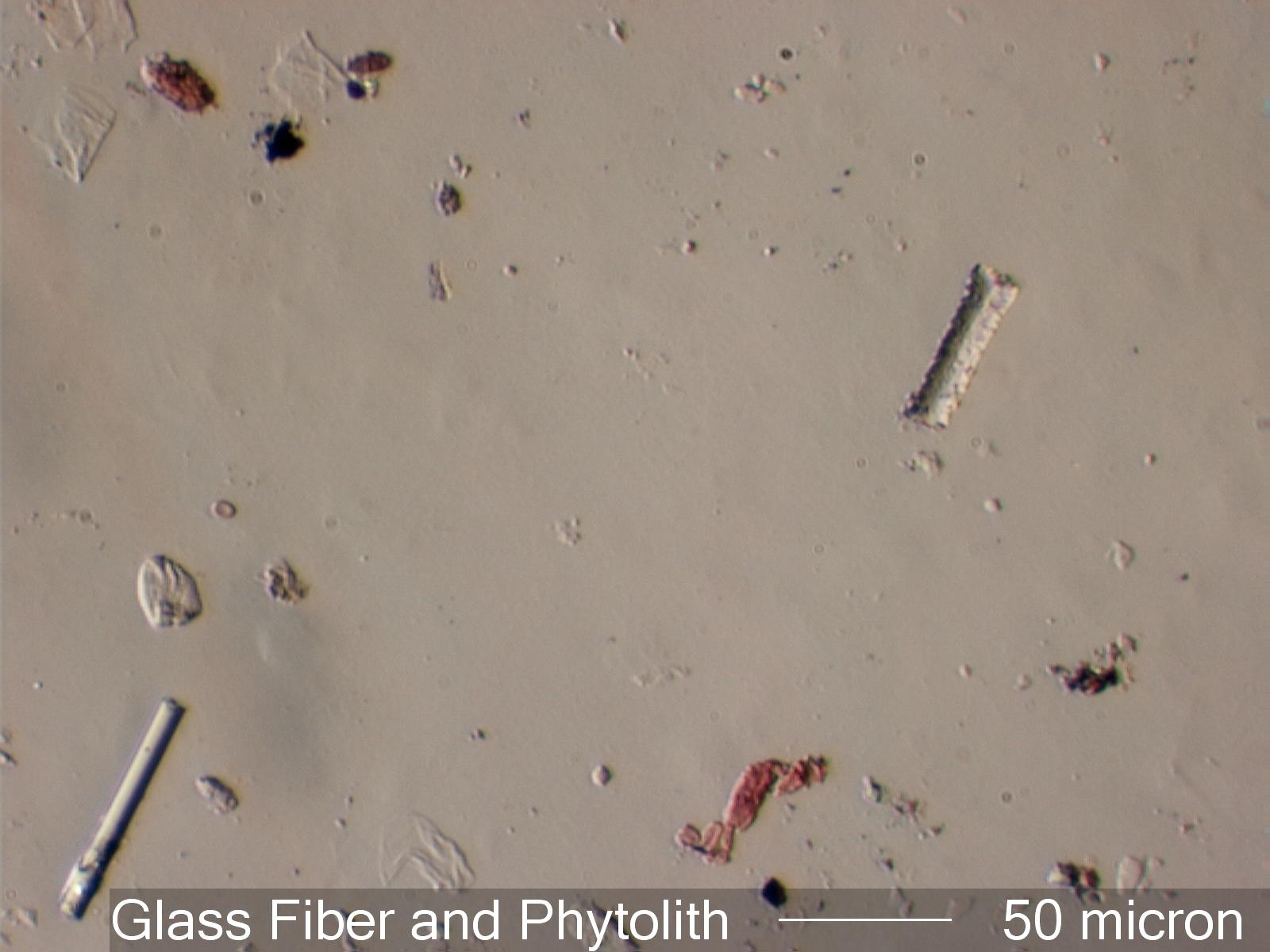 . . . CalciteCalcite has an omega refractive index of 1.658 or higher (in this case 1.669) and an epsilon prime refractive index in this orientation of about 1.550. The first image shows the relief created when a linear polarizer is oriented to show epsilon prime. The refractive index difference is 0.114. The result is high relief. The second image is with the crystal rotated 90 degrees, showing the omega refractive index. The difference is 0.005 refractive index units. The result is low relief. In this position, lowering the stage results in a orange Becke' line moving into the particle and an blue Becke' line moving out, as shown in the third image. If Oblique illumination is used the dispersion staining colors are evident on oposite sides of the crystal. 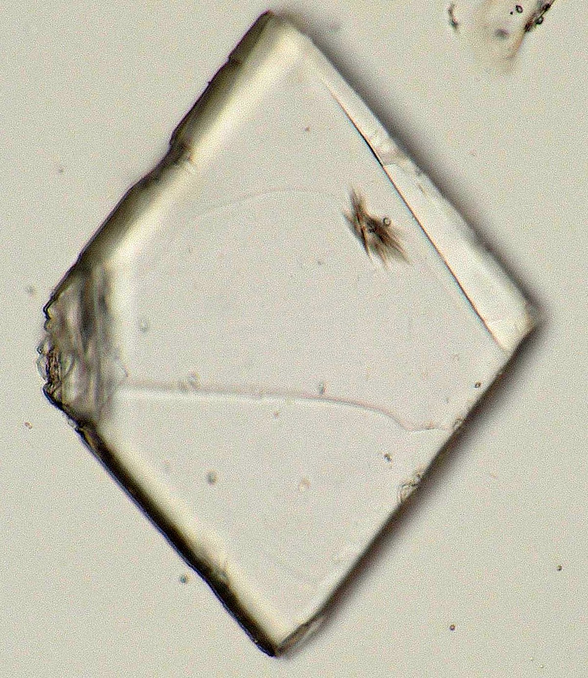
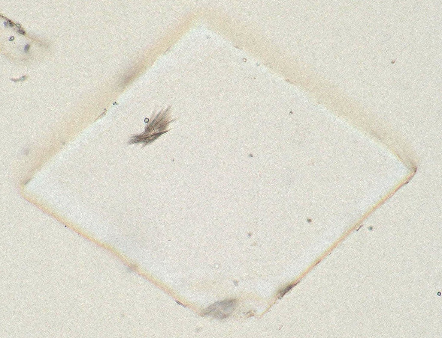
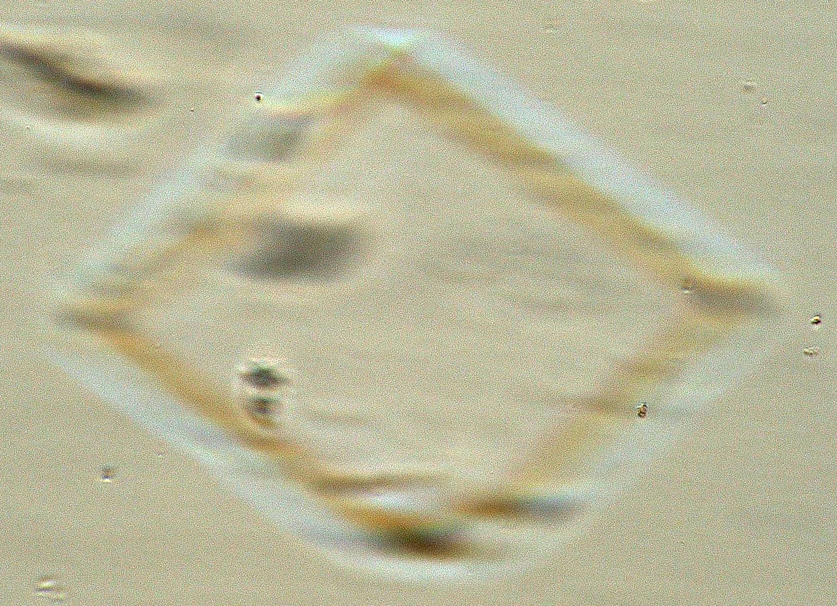
. . . Calcite and Glass Standards in 1.664The optical glasses have a refractive index of 1.64, 1.66, and 1.67. The first image shows the calcite crystal in high relief and the 1.67 refractive index glass in low relief. The 1.66 refractive index glass is invisible. With oblique illumination, the second image, the optical glasses show dispersion staining colors. 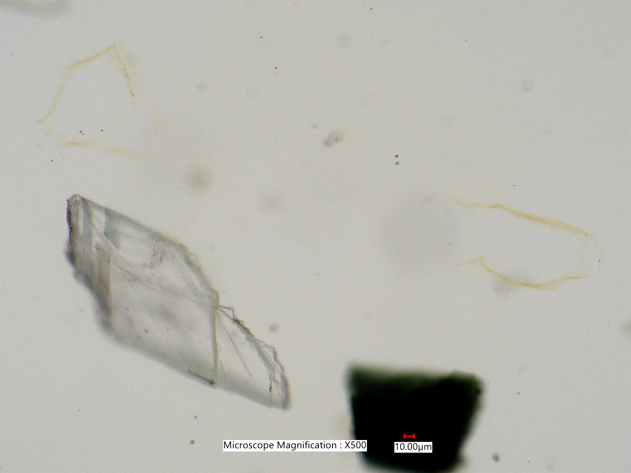
. . . Olivine and Quartz in 1.664 Refractive index MediumThe first image shows the olivine (upper left) and quartz (lower center) in
slightly off crossed polarized light.
Dispertion Staining. . . Dispertion Staining Color ChartsDispersion Staining Color Charts are approximations of the colors shown by a particles that matches the refractive index of the mounting medium at a specific wavelegnth in the visible part of the electromagnetic spectrum. The colors vary slightly in the real world as a result of the size and shape of the particle, the type of dispertion staining used, and the physical configuration and design of the microscope. 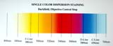
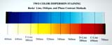
. . . Dispertion Staining StandardsThis section shows Cargille Standard Optical Glasses in Standard Cargille High Dispersion Refractive Index Liquids. The intent is to demonstrate the effects of size and of different microscope configurations on the colors. Rotation of PolarizationIf the refractive index of a transparent particle is much different than the medium in contact with it, then the polarized beam can be changed at the interface as a result of reflection. If the interface is aligned with the polarizer or analyzer then the beam is not affected. In other orientations reflection at the interface results in rotation of the polarized beam and the interface appears to show a first order white interference color. 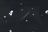
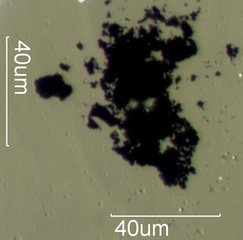
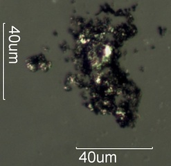
Diffraction EffectsOblique PropertiesInterface Kerr Effect?Polarized light is depolarized at the interface between a conductive particle and a non-conductive mounting medium. This light halo effect with transmitted crossed polarized light indicates an opaque particle is a wear metal particle or at least is conductive. Graphite is sufficiently conductive to produce this effect. Pencil debris can be distinguished from combustion residue by this effect. . . . . . . Fretting Metal Wear
. . . . . . Graphite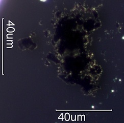
. . . . . . Magnetite Spheres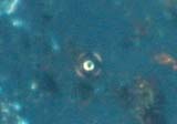
DiffractionFine structure can act as a diffraction grating. ReflectionReflection at an interface is a function of the difference in the real part of the refractive index between the particle and the medium. Contrast EnhancementThere are literally hundreds of ways to enhance contrast at the edge of a particle. Simply using crossed polarized light for birefringent partices is one example. Phase contrast and any of the other hundreds of interference methods are examples. Rhineberg filters and darkfield illumination are two more examples. Selecting a contrasting refractive index mounting medium is an important consideration in desiding whether the surface features or interial structuctures of the particles are of interest. A few of those methods are shown here. . . . Selection of Mounting MediumIf the mounting medium is near the refractive index of the particle then any internal materials with a different refractive index or bondaries become more easily visible. Surface features become less apparent. if a mounting medium with a very different refractive index is selected, then surface features become easy to visuallize. . . . Reduced Substage IrisReducing the angle of the cone of light impinging on the particle increases contrast but decreases resolution. . . . Oblique IlluminationOblique illumination increases resolution normal the the axis of the illuminating beam but decreases the resolution for structures parallel to the projection of the axis on the stage. It also distorts the image to some extent, exagerating the shape of the particle perpedicular to the axis of the illuminating beam. . . . Darkfield IlluminationDarkfield illumination makes all particles, even opaque particles, bright on a dark field of view. This is an advantage for automated particle counts and particle obscuration measurements. Resolution is increased. . . . Rheinberg FiltersRheinberg filters can create color contrast and can be used to balance brightness for the objects in the field of view relative to the background. . . . Other Substage StopsModifying the shape or the angle of the illuminating beam relative to the optic axis of the microscope can create a number of different effects. . . . Polarized LightAnisotropic particles become easily visible when crossed linear polarized light is used, dependent on the orientation of the particle. If circular polarized light is used then the contrast is no longer dependent on orientation. 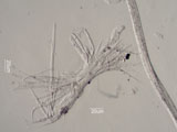
. . . Phase ContrastPhase contrast is best used with particles that have low contrast when viewed with brightfield illumination. Phase contrast can be positive or negative and have a variety of other characteristics that may better suit a specific application. . . . Interference SystemsNomarski, Jamin-Lebedeff, Mach-Zehnder, Hoffman, and many other systems that alter the diffraction beam path to bring it into interference with the image beam path create contrast. Many of these systems can be used quanitatively to measure a few nanometers difference in pathlengths. |
