
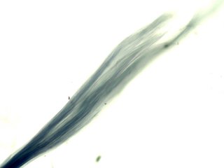
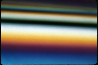
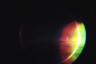
Topics in Light MicroscopyAnomalous BirefringenceAnomalous birefringence is simply the result of a material's birefringence changing in a significant way as a function of the wavelenght of light. It produces anomalous interference colors in the material being examined between crossed polarizing filters. Crocidolite, Higher Birefringence in Red Light (longer Wavelengths) Very thin fibers appear red between crossed polarizing filters. Thicker fibers appear blue because of the strong blue color of the mineral. 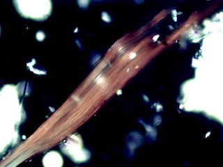
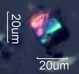
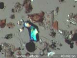
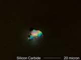
Silicon Carbide, Higher Birefringence in Blue Light (Shorter Wavelenghts) Blue wavelengths cycle more rapidly than red wavelengths. Yellow interference color begins for thinner particles and first order red appears purple because blue is increasing well before red significantly decreases. This effect changes the color sequence through the whole range of microscopic silicon carbide particles. 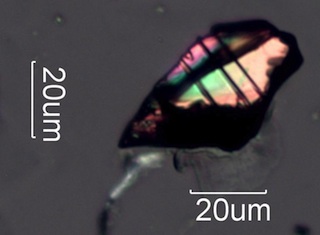
Apparent Birefringence
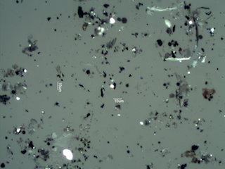
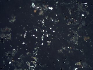
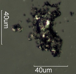
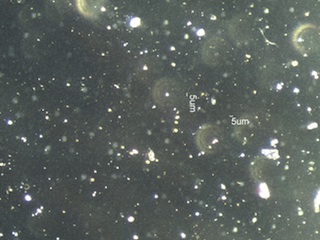
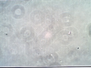
Edge Effect BirefringencePolarized light is depolarized at the interface between a conductive particle and a non-conductive mounting medium. This light halo effect with transmitted crossed polarized light indicates an opaque particle is a wear metal particle or at least is conductive. Graphite is sufficiently conductive to produce this effect. Pencil debris can be distinguished from combustion residue by this effect. 
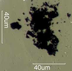
Graphite 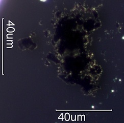
Magnetite Spheres 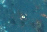
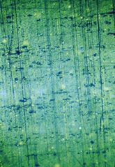
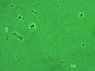
Stress Birefringence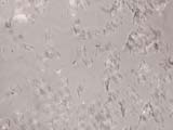 Birefringence from Plastic Deformation in Human Skin Cells
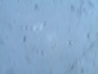
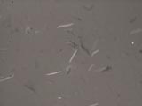 Birefringence from Plastic Deformation in Dog Skin Cells
 Stress Birefringence in Safety Glass
Resolution vs Visibility Through the MicroscopeSimple Illumination Methods


Resolution and Ocular Magnification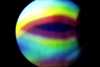
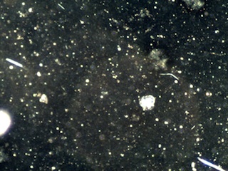
Brightfield vs Darkfield Illumination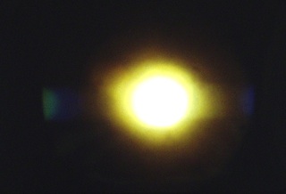
Brightfield vs Oblique Illumination
TN.jpg)
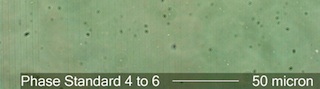
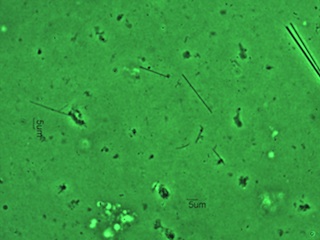
Phase Contrast vs Visibility Through the Microscope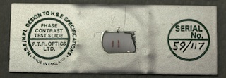
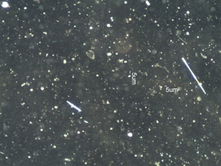
Polarized Light vs Visibility Through the Microscope
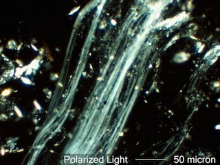
Asbestos Fibers and Visibility Through the Light Microscope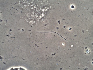
|
