
The Light Microscope as an Optical Bench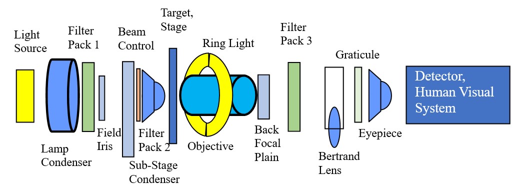
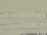
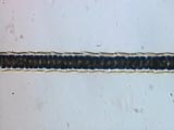
Morphological PropertiesFeatures evident with transmitted brightfield, oblique, darkfield, or reflected brightfield, darkfield, oblique, or grazing incident illumination. . . . Projected ShapeThe projected shape of a particle is its transmitted light outline. These shapes can be very helpful in determining the type of particle present. Fibers are an obvious example. The shape alone eliminates a huge range of possibilities. One of the first steps in keying out a pollen grain is to classify its outline. Shape, as used here, is distinct from angularity or roundness. Those are details handled later in this section. . . . Fibers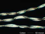
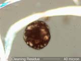
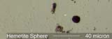
. . . CirclesCircles may be the result of a liquid deposition or a growth pattern. The projected shape is not sufficient to determine if the particle is spherical. 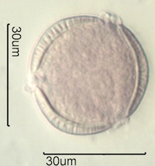
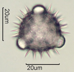
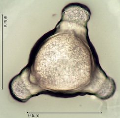
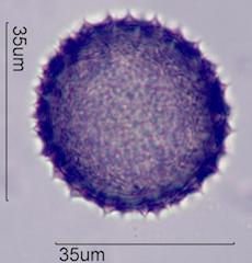
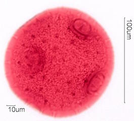
. . . PollensPollens come in many shapes and vary in size from a few micrometers to hundreds of micrometers. Most are in the range of 15 to 100 micrometers. The wall of a pollen grain consists of at least two distinct layers and as many as four distinct layers that may be separated by characteristic pillar structures. 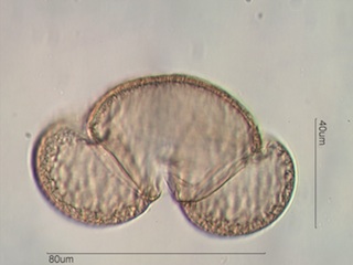
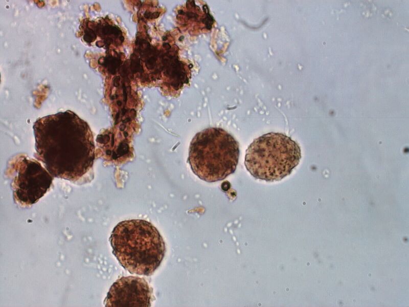
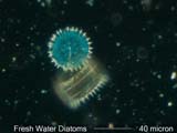
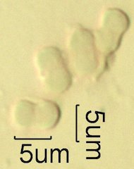
. . . SporesSpores come in many shapes but tend to be smaller than most pollens, often have a visible attachment point, and a single layer membrane wall. . . . DiatomsDiatoms can be divided into two broad types, Pennate and Centric, though there are also intermediate shapes. Pennate diatoms are elongated, have one axis much longer than the other two. Centric diatoms have one shorter axis and the other two are similar giving the diatom a circular or slightly ellipsoidal shape. . . . Tapered CylindersTapered cylinders are created by a unidirectional force. In the case of tire wear it is the friction of the tire against the road. In the case of some combustion sources it is the shrinkage created by the advancing thermal gradient. . . . GlobularGlobular particles are particles with internal and external centers of curvature over their surface. . . . Straight EdgesStraight edges indicate a linear structural element that may be a cleavage surface, a growth pattern or a linear force that generated the particle. . . . RosettesRosettes are the result of growth outward from a central nucleation point. 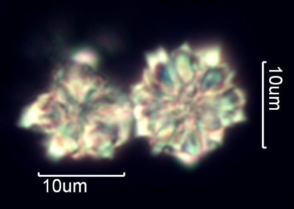
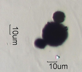
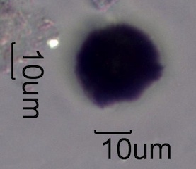
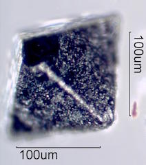
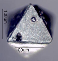
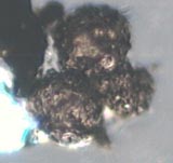
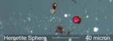
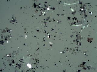
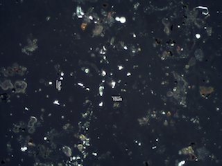
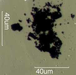
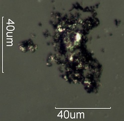
. . . DendritesDendrites are branching structures were the truck and the branches have the same diameter. These are common as a result of electrostatic deposition, some chemical reactions, and some skeletal crystal growth habits. . . . Reflected ShapeReflected darkfield illumination revels three dimensional aspects of a particles shape not evident with transmitted light. The magnetite particles below are an example. Charred biomass is another good example. Without reflected darkfield the identity of these opaque particles is in question. 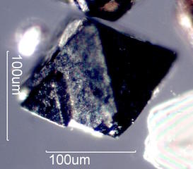
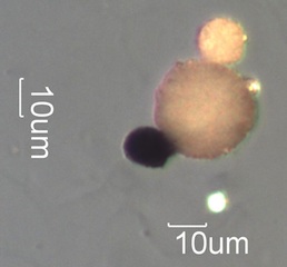
. . . SizeSize is a far more complex issue than might seem to be the case. It is simple for a circle, but quickly becomes more difficult as the aspect ratio increases or the length of the perimeter significantly exceeds the perimeter of the enclosed circle. There are a number of standard approaches. If bridging is a concern then the longest dimension of the particle is its size. If the concern is a sieve size then then the larger of the two smallest dimensions is the size. The average of 6 or more Ferrets is another standard measure. Other measures include the diameter of the enclosing circle, the diameter of the enclosed circle, The projected intercept with a line at a fixed angle, . . . . . . . Circles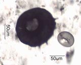
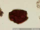
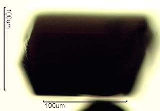
 . . . Aspect Ratio, Length/Width. . . Angles. . . Angularity. . . Surface Texture. . . Internal Texture. . . Transmitted Scatter. . . Reflected Scatter. . . Surface Features. . . Internal Features. . . Cross-Section. . . Mixed Phase Structure. . . SymmetryPhysiochemical PropertiesFeatures evident as a result of chemical composition, crystallography, or special arangment of molecules, ions, electron bond features, or excitation effects that can be made visible. Illumination systems include polarized light, phase contrast, interference systems, fluorescence, etc. . . . Transmission. . . AbsorptionAbsorption is the light lost in the particle that is converted from electromagnetic energy into thermal energy. Absorption is often wavelength dependent and contributes to the apparent color of the particle. . . . . . . HemetiteHematite has a complex refractive index of 2.937 + i(0.24268) for epsilon. The omega refractive index is about 3.2 + i(0.1) at the same wavelength. When using transmitted light hematite appears nearly opaque. With its high birefringence, approximately 0.28, even small particles appear red between crossed polarizing filters. It appears red because it transmits red wavelengths much more efficiently than the shorter wavelengths (blue, green, yellow). With Brightfield illumination the background is too bright to see the small amount of red light transmitted. With crossed polarizers the background is dark and the light transmitted as a result of the high birefringence of hematite is red. 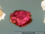
. . . . . . TourmalinePolished sections of tourmaline were the first linear polarizing filters. 
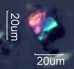
. . . Reflectivity. . . Transmission Color. . . Reflected Color. . . BirefringenceBirefringence is the property of showing more than one refractive index as a function of particle orientation and wavelength. Such a particle will exhibit interference colors when viewed between crossed circular polarized filters. They will typically show extinction positions (see below) with rotation of the stage when viewed between crossed linear polarizing filters. . . . . . . Low Birefringence. . . . . . Moderate Birefringence. . . . . . High Birefringence. . . . . . Anomalous BirefringenceAnomalous birefringence is the result of birefringence varying by wavelength. The result is anomalous interference colors. Silicon carbide and crocidolite asbestos are two common examples. Crocidolite has higher birefringence in red light (longer Wavelengths) than in blue. As a result, very thin fibers of crocidolite appear red between crossed polarizing filters. Thicker fibers appear blue because of the strong blue color of the mineral. 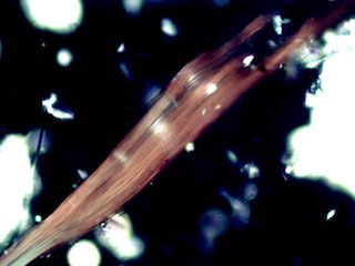
Silicon carbide has higher birefringence in blue light (Shorter Wavelenghts) than in red. As a result, blue wavelengths cycle more rapidly than red wavelengths. Yellow interference color begins for thinner particles and first order red appears purple because blue is increasing well before red significantly decreases. This effect changes the color sequence through the whole range of microscopic silicon carbide particles. 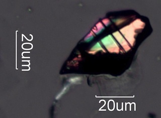
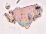
. . . . . . Stress BirefringenceWhen a material is placed under stress the distribution of the electrons in the material is changed. The amount of change is different for each material and is a characteristic of the material. The photoelastic constant of the matrial is a measure of the electron displacement (strain) as a function of the load (stress) applied as long as the deformation is elastic, springs back when the load is removed. If the Young's Modulus of the matrial is exceeded, then some of the deformation becomes permenant. In some materials the applied load can be "frozen" in place, as in the case of high stress glass sheet. Polarized light can make the displacement visible. Both plastic deformation and elastic deformation result in an anisotropic distribution of electrons in the material that becomes visible as interference colors when the object is viewed between crossed linear or crossed circular polarizing filters. Click on the photographs below for more information. . . . . . . . . . Stress Birefringence in Skin Cells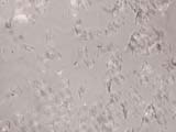
. . . . . . . . . Stress Birefringence in Safety Glass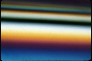
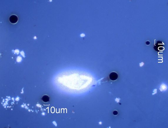
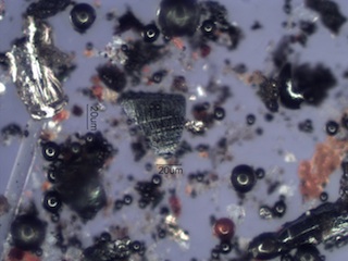
. . . . . . Conductivity Birefringence (Hall Effect?)Polarized light is depolarized at the interface between a conductive particle and a non-conductive mounting medium. This light halo effect with transmitted crossed polarized light indicates an opaque particle is a wear metal particle or at least is conductive. Graphite is sufficiently conductive to produce this effect. Pencil debris can be distinguished from combustion residue by this effect. . . . . . . . . . Fretting Metal Wear
. . . . . . . . . Graphite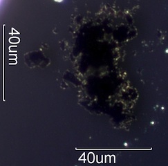
. . . . . . . . . Magnetite Spheres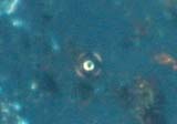
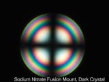
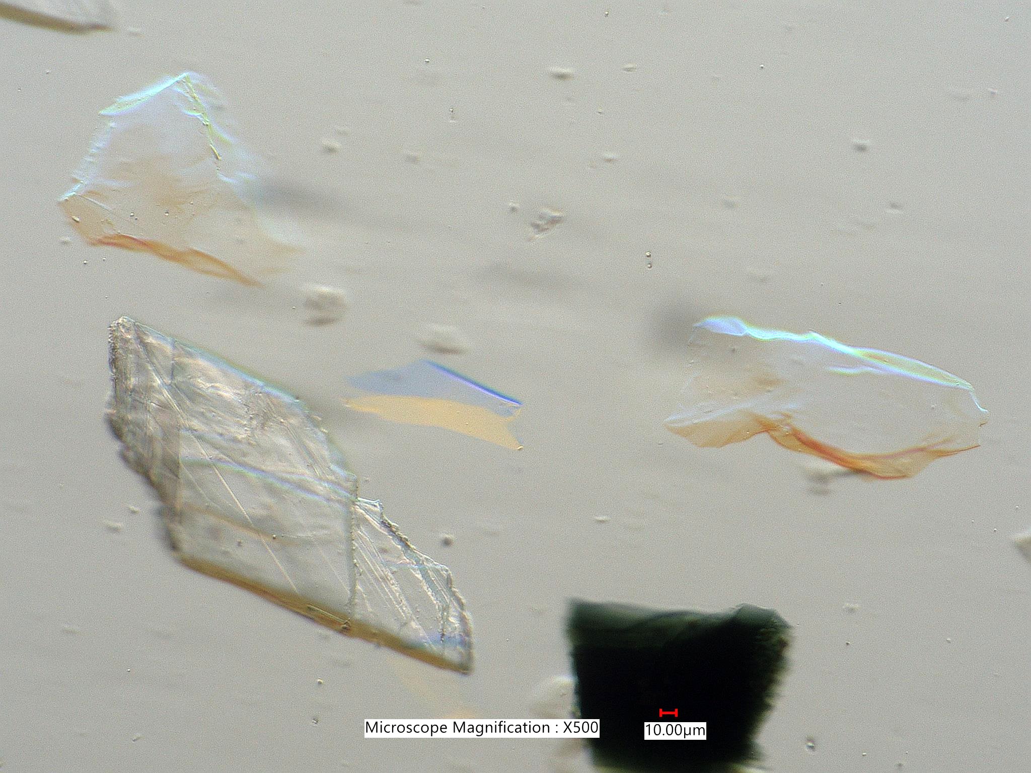
. . . . . . Form Birefringence. . . . . . False BirefringenceIf the refractive index of a transparent particle is much different than the medium in contact with it, then the polarized beam can be changed at the interface as a result of reflection. If the interface is aligned with the polarizer or analyzer then the beam is not affected. In other orientations reflection at the interface results in rotation of the polarized beam and the interface appears to show a first order white interference color. 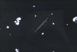
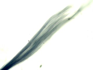
. . . Bireflectivity. . . PleochroismPleochrism is the property of changing color on rotation when viewed with linear polarized light. Many colored materials show this property. . . . . . . Crocidolite
. . . . . . Hornblende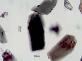
. . . . . . Tourmaline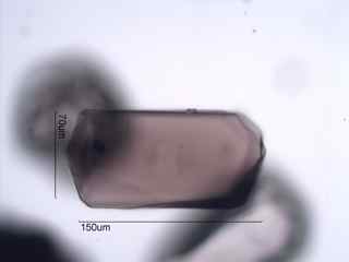
. . . . . . Olivine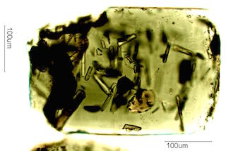
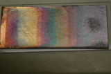
. . . Interference ColorsInterference colors may result from birefringence or from thin film effects. . . . . . . Thin Film Interference Colors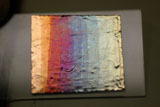
. . . . . . Birefringence Interference Colors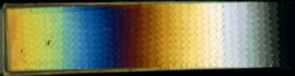
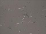
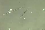
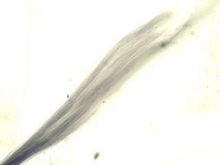
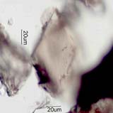
. . . Twinning. . . Extinction. . . Interference Pattern. . . FluorescenceInterface PropertiesFeatures evident at the interface between the particle and the adjacent medium. . . . ReliefRelief, simply speaking, is the contrast at the edge of a particle as a result of differences in the refractive index between the particle and the mounting medium. John Delly provides a more detailed definition in his book, ESSENTIALS OF POLARIZED LIGHT MICROSCOPY AND ANCILLARY TECHNIQUES. His definition is "Contrast between a specimen and its surroundings (typically mounting media) due to the difference between their refractive indices. The greater the numerical difference in refractive indices, the stronger the relief. Expressed as positive or negative; high, medium, or low." . . . . . . Glass Fiber and Silica Phytoliths in 1.485 refractive index mounting mediumThe first image shows a glass fiber from an office ceiling acoustic tile. The refractive index of the glass fiber is about 1.520. The relief is moderate. The sign cannot be determined, positive or negative, from this image. If it were negative, refractive index lower than the mounting medium, then the fiber would become dark when the stage is lowered (bright Becke line out). If it were positive, refractive index higher than the mounting medium, then the fiber would become bright when the stage is lowered (bright Becke line in). 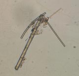
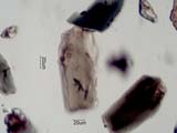
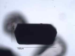
This image shows a glass fiber (lowere left) and a silica phytolith (upper right) with oblique illumination. The light is coming in from the right. The silica phytolith has a lower refractive index, relief is negative, and so is bright on the right. The glass fiber has a higher refractive index, relief is positive, and is dark on the right side. With oblique illumination the relative refractive index can be determined without having to defocus the particle. 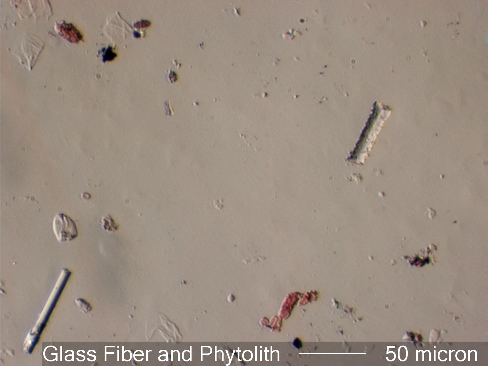 . . . . . . CalciteCalcite has an omega refractive index of 1.658 or higher (in this case 1.669) and an epsilon prime refractive index in this orientation of about 1.550. The first image shows the relief created when a linear polarizer is oriented to show epsilon prime. The refractive index difference is 0.114. The result is high relief. The second image is with the crystal rotated 90 degrees, showing the omega refractive index. The difference is 0.005 refractive index units. The result is low relief. In this position, lowering the stage results in a orange Becke' line moving into the particle and an blue Becke' line moving out, as shown in the third image. If Oblique illumination is used the dispersion staining colors are evident on oposite sides of the crystal. 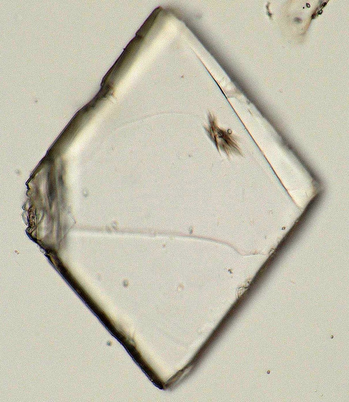
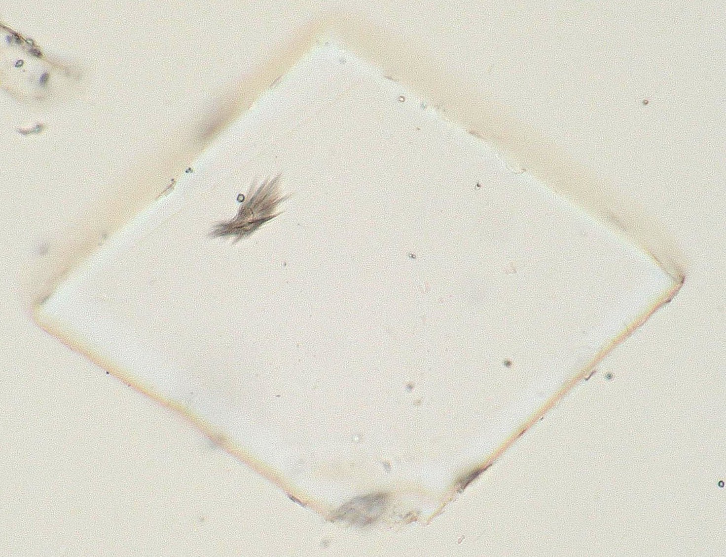
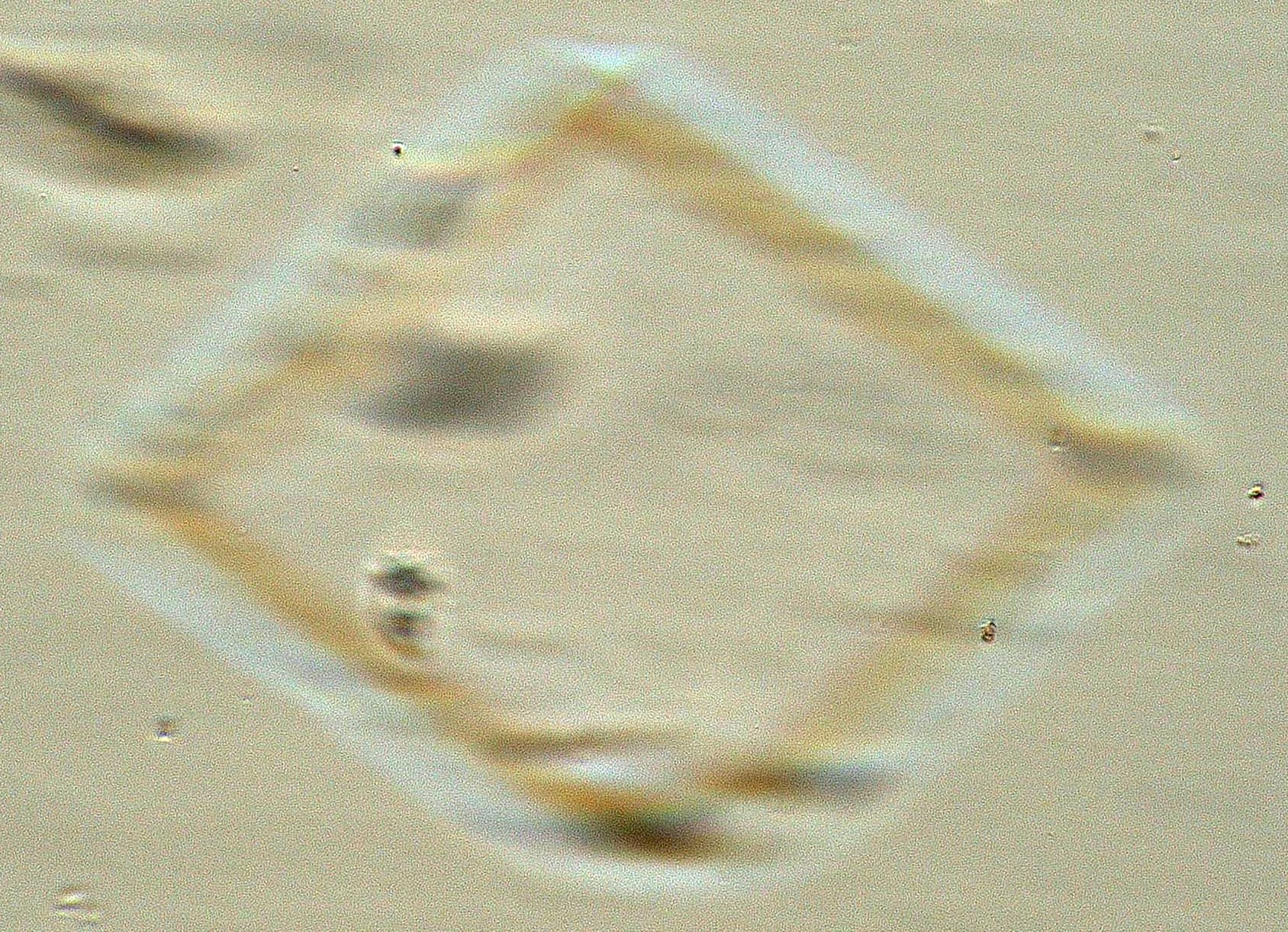
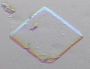
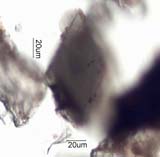
. . . . . . Calcite and Glass Standards in 1.664The optical glasses have a refractive index of 1.64, 1.66, and 1.67. The first image shows the calcite crystal in high relief and the 1.67 refractive index glass in low relief. The 1.66 refractive index glass is invisible. With oblique illumination, the second image, the optical glasses show dispersion staining colors. 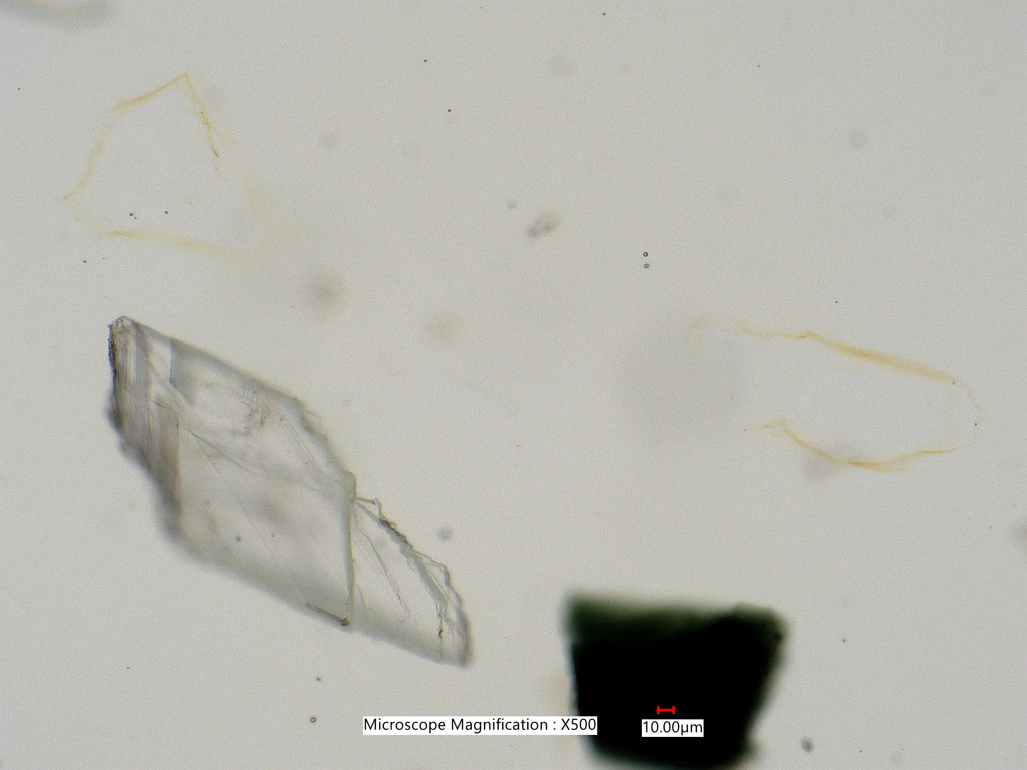
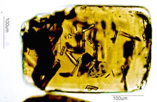
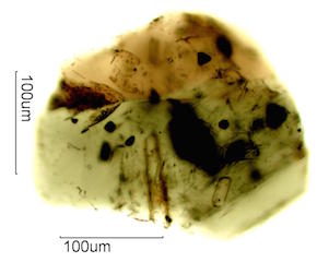
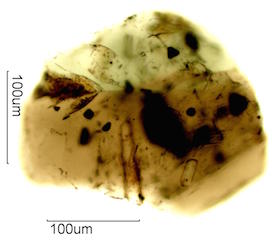
. . . . . . Olivine and Quartz in 1.664 Refractive index MediumThe first image shows the olivine (upper left) and quartz (lower center) in
slightly off crossed polarized light.
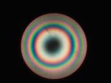
. . . Relative Refractive Index. . . Relative Absorption. . . Dispertion Staining. . . . . . Dispertion Staining Color ChartsDispersion Staining Color Charts are approximations of the colors shown by a particles that matches the refractive index of the mounting medium at a specific wavelegnth in the visible part of the electromagnetic spectrum. The colors vary slightly in the real world as a result of the size and shape of the particle, the type of dispertion staining used, and the physical configuration and design of the microscope. 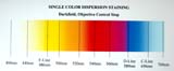
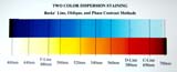
. . . . . . Dispertion Staining StandardsThis section shows Cargille Standard Optical Glasses in Standard Cargille High Dispersion Refractive Index Liquids. The intent is to demonstrate the effects of size and of different microscope configurations on the colors. . . . Rotation of PolarizationIf the refractive index of a transparent particle is much different than the medium in contact with it, then the polarized beam can be changed at the interface as a result of reflection. If the interface is aligned with the polarizer or analyzer then the beam is not affected. In other orientations reflection at the interface results in rotation of the polarized beam and the interface appears to show a first order white interference color.
. . . Diffraction Effects. . . Oblique Properties |
